Solar Panel Simulator (SPS)
| Responsible |
|
| Last Updated | 10/12/2025, 12:48:54 PM |
| Last Author | Kai Berszin |
Scope
This document specifies the Solar Panel Simulator (SPS).
The Solar panel simulator is a hardware device simulating the behaviour of a single Solar Panel used in the SAGE CubeSat mission.
Requirements
- The SPS shall be able to emulate a Endurosat 3U Solar Panel
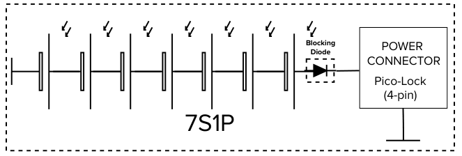
- The SPS shall emulate a 7S1P configuration of lightricity cells (TBD)
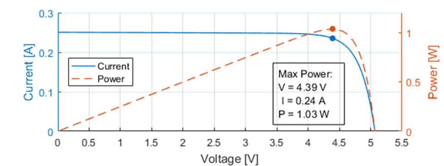
- The SPS shall work as a constant current source with the current given by the characteristic IV curve of the simulated solar panel and input paramters.
- The SPS shall support a maximum output voltage of 20V
- The SPS shall support a maximum output current of 750mA
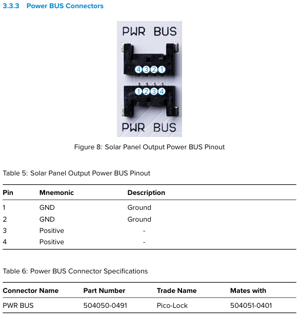
- The SPS shall output the emulated solar panel using a 4-pin Molex Pico-Lock connector compatible with the Endurosat Pinout
- The SPS shall emulate a blocking diode connected in series with the cell string.
- The SPS shall emulate a 7S1P configuration of lightricity cells (TBD)
- The SPS shall be powered using an external 24V min. 1A power supply.
- The SPS shall feature both a banana-style as well as barrel-jack power connector
- The characteristic parameters of the SPS shall be reconfigurable on-the-fly
- The SPS shall be configured over an external communication interface.
- The SPS shall have a UART communication interface.
- The SPS may have a I2C communication interface, in this case:
- The SPS shall be an I2C slave.
- The SPS shall feature a switch to select the I2C slave address supporting at least 4 possible choices.
- All communication interfaces shall feature electrical isolation between the common communication bus/host and the SPS.
- All communication interfaces shall be exposed using Molex Picolock connectors.
- The SPS shall calculate the output of the IV curve given an illumination value on the fly in the control loop.
- The SPS shall receive the following characteristic paramters and store them persistently:
- The maximum current at full illumination
- The cell diode parameters for effective thermal voltage and saturation current
- The bypass diode parameters for effective thermal voltage and saturation current
- The value for the cell shunt resistance and cell ceries resistance .
- The SPS shall receive the value for the current illumination
- The illumination shall be 0 upon start up.
- The SPS shall receive the following characteristic paramters and store them persistently:
- The SPS shall be configured over an external communication interface.
- The SPS may feature a display showing the current configuration and ouput paramters (Voltage, Current)
Background
PV Cell
The internal resistance of an solar cell is not constant and is depended on external factors such as illuminance and temperature.
To maximise the extracted power the load resistance needs to be actively controlled s.t. the internal resistance ~= load resistance.
This provides a characteristic curve of current vs voltage, the IV curve, for constant external conditions.
To maximize this Maximum Power Point Tracking (MPPT) is deployed to find the optimal operating point.
A single solar cell can be described as the following equivalent circuit
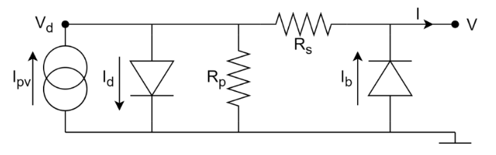 .
.
and the following equation:
For more information refer to the paper given in [1].
Endurosat Solar Panels
The EnduroSat panel is fitted using 7 PV cells connected in series (7S1P).
The connector is a 4-pin Molex pico-lock with the following pinout:
References
A similar hardware device is already openly available, including a good paper1 describing the design.
Appendix
Lambert W function in C
This is an modified version based on ChatGPT. It is assumbed that the input
#include <math.h>
#include <stdint.h>

// Define tolerance and maximum iterations
#define LAMBERT_W_TOL 1e-6
#define LAMBERT_W_MAX_ITER 10000 // find sweet spot for this number

// Lambert W function (for x > 0)
double lambertW(double x) {
    // W(0) = 0
    if(x == 0) {
        return 0;
    }

    // Initial approximation based on log(x)
    double w = log(x);

    // Refine approximation iteratively using Halley's method
    for (int i = 0; i < LAMBERT_W_MAX_ITER; i++) {
        double ew = exp(w);
        double wew = w * ew;
        double wewx = wew - x;
        double denominator = ew * (w + 1.0) - ((w + 2.0) * wewx / (2.0 * w + 2.0));
        double delta = wewx / denominator;

        w -= delta;

        if (fabs(delta) < LAMBERT_W_TOL) {
            break;
        }
    }

    return w;
}
Cell Current given Voltage in Matlab
This function originates from the MIST SPS.
The lambertw function is given in the symbolic library.
An approximation in C is given in the chapter above.
%   Vc: Voltage(s) to calculate at, column vector.
%   i: Illumination to calculate at, scalar.
% OUTPUT:
%   Ic: Current(s) calculated, column vector.
function Ic = getCellCurrent( Vc,i )
% Cell parameters in SI units
Imax = 0.5009;
Vd_t = 0.1135;
Id_sat = 10^-10;
Vb_t = 0.03;
Ib_sat = 1e-3;
Rs = 0.04;
Rp = 400;

theta = @(V,Ipv) (Rs*Id_sat)/Vd_t * exp((Rs*Ipv+V)/Vd_t);
I = @(V,Ipv) Ipv -V/Rp -Vd_t/Rs*lambertw(theta(V,Ipv)) +Ib_sat*(exp(-V/Vb_t)-1);

Ic = I(Vc,i*Imax);
end