P31u Hardware
This document contains confidential data and is not intended to be shared outside of SAGE!
| Authors |
|
| Responsible |
|
| Last Updated | 10/12/2025, 12:48:54 PM |
| Last Author | Kai Berszin |
Scope
This page describes the hardware of the P31u power conditioning unit.
Options
The following options were chosen during ordering:
General
| Parameter | Value |
|---|---|
| Battery Configuration | BP4 (16.8V) |
| Stack Connector | P31u: B, BP4: F |
| I2C pull-up | populated |
| Kill Switch | Non-locking |
| Conformal coating | None |
Stack connector B : SSQ-126-03-G-D
Power Outout Options
| Pin | Name | Buck Converter | Current limit |
|---|---|---|---|
| H1-47 | OUT-0 | 3V3 | 2.5 A |
| H1-49 | OUT-1 | 3V3 | 2.5 A |
| H1-51 | OUT-2 | 5V0 | 2.5 A |
| H1-48 | OUT-3 | 3V3 | 2.5 A |
| H1-50 | OUT-4 | 5V0 | 2.5 A |
| H1-52 | OUT-5 | 5V0 | 2.5 A |
Pinout
Top
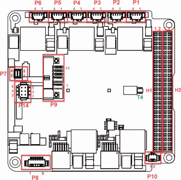
H1/H2 Stack Connectors
| Pin | Mnemonic | Dir | Description |
|---|---|---|---|
| H1-32 | 5 V_in | I | 5 V battery charge input (Same as P8 pin 6) |
| H1-41 | I2C-SDA | I/O | I2C serial data |
| H1-43 | I2C-SCL | I/O | I2C serial clock |
| H1-47 | OUT-1 | O | Latch-up protected output |
| H1-49 | OUT-2 | O | Latch-up protected output |
| H1-51 | OUT-3 | O | Latch-up protected output |
| H1-48 | OUT-4 | O | Latch-up protected output |
| H1-50 | OUT-5 | O | Latch-up protected output |
| H1-52 | OUT-6 | O | Latch-up protected output |
| Pin | Mnemonic | Dir | Description |
|---|---|---|---|
| H2-25 | +5 V | O | Permanent 5 V output |
| H2-26 | +5 V | O | Permanent 5 V output |
| H2-27 | +3.3 V | O | Permanent 3.3 V output |
| H2-28 | +3.3 V | O | Permanent 3.3 V output |
| H2-29 | GND | O | Power ground |
| H2-30 | GND | O | Power ground |
| H2-31 | AGND | O | Analogue ground |
| H2-32 | GND | O | Power ground |
| H2-45 | V_BAT | O | Battery voltage |
| H2-46 | V_BAT | O | Battery voltage |
P1 - Solar Input
Picoblade 4 pin. Solar panel input connectors.
| Pin | Usage |
|---|---|
| 1 | GND |
| 2 | GND |
| 3 | Vsc |
| 4 | Vsc |
P2 - Solar Input
Picoblade 4 pin. Solar panel input connectors.
| Pin | Usage |
|---|---|
| 1 | GND |
| 2 | GND |
| 3 | Vsc |
| 4 | Vsc |
P3 - Solar Input
Picoblade 4 pin. Solar panel input connectors.
| Pin | Usage |
|---|---|
| 1 | GND |
| 2 | GND |
| 3 | Vsc |
| 4 | Vsc |
P4 - Solar Input
Picoblade 4 pin. Solar panel input connectors.
| Pin | Usage |
|---|---|
| 1 | GND |
| 2 | GND |
| 3 | Vsc |
| 4 | Vsc |
P5 - Solar Input
Picoblade 4 pin. Solar panel input connectors.
| Pin | Usage |
|---|---|
| 1 | GND |
| 2 | GND |
| 3 | Vsc |
| 4 | Vsc |
P6 - Solar Input
Picoblade 4 pin. Solar panel input connectors.
| Pin | Usage |
|---|---|
| 1 | GND |
| 2 | GND |
| 3 | Vsc |
| 4 | Vsc |
P7 - ARM Connector
(2x2 2.54 mm male-header) Battery ARM connector: This connects the batteries to the P31u circuitry.
| Pin | Usage |
|---|---|
| 1 | Vbat cell terminal |
| 2 | Vbat system |
| 3 | Vbat cell terminal |
| 4 | Vbat system |
P8 - Flight Preparation Panel
P8 : (Picoblade 6 pin) Flight preparation panel connector
| Pin | Usage | Description |
|---|---|---|
| 1 | GND | |
| 2 | RBF | RBF pin on P8 must be shorted to ground to engage |
| 3 | KS | KS on P8 must be shorted to ground to override kill switch (switch on P31u). |
| 4 | KS_RESET | KS_RESET on P8 must be shorted to ground to engage reset. |
| 5 | Vbat (through 100kOhm) | KS on P10 and P11 Is used for measuring the battery voltage, is useful when the batteries should be charged |
| 6 | CHARGE | 5 V Charging interface on photovoltaic power converter no.3 |
P9 (Not used)
This pin is not used for SAGE.
For more information refer to the P31u datasheet.
P10 - Kill switch
(Picoblade 2 pin) Kill switch connectors
| Pin | Usage | Description |
|---|---|---|
| 1 | KS- (GND) | KS on P10 and P11 is a two-pin connector that must be shorted to switch on P31u, alternatively KS+ can be shorted to any ground common with P31u. |
| 2 | KS+ | KS on P10 and P11 is a two-pin connector that must be shorted to switch on P31u, alternatively KS+ can be shorted to any ground common with P31u. |
P14 - Optional Battery Ground Break Connector
(Harwin M80-8280642) Optional battery ground break connector
| Pin | Usage |
|---|---|
| 1 | GND |
| 2 | Battery minus (BAT GND) |
| 3 | GND |
| 4 | Battery minus (BAT GND) |
| 5 | GND |
| 6 | Battery minus (BAT GND) |
Bottom
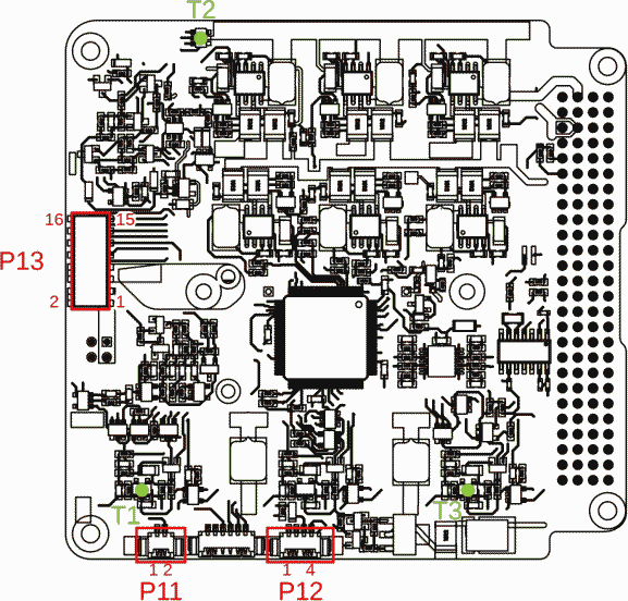
P11 - Kill switch
(Picoblade 2 pin) Kill switch connectors
| Pin | Usage | Description |
|---|---|---|
| 1 | KS- (GND) | KS on P10 and P11 is a two-pin connector that must be shorted to switch on P31u, alternatively KS+ can be shorted to any ground common with P31u. |
| 2 | KS+ | KS on P10 and P11 is a two-pin connector that must be shorted to switch on P31u, alternatively KS+ can be shorted to any ground common with P31u. |
P12 - GOSH Interface
(Picoblade 4 pin) Serial connector for GOSH interface.
| Pin | Usage |
|---|---|
| 1 | GND |
| 2 | Not Connected |
| 3 | RxD |
| 4 | TxD |
P13 - to NanoPower BP4
Battery board extension connector for BP4.
he battery cells are connected to a 16-pin dual row 2 mm pitch female header. This connector fits with the female external battery connector of the GomSpace NanoPower BP4 with a Samtec TW-08-07-G-D-375-188 in between.
| Pin | Name | Description |
|---|---|---|
| 1 | Vbat | Battery voltage connection |
| 2 | Vbat | Battery voltage connection |
| 3 | Vbat | Battery voltage connection |
| 4 | Vbat | Battery voltage connection |
| 5 | GND | Ground |
| 6 | GND | Ground |
| 7 | GND | Ground |
| 8 | GND | Ground |
| 9 | MOSI | SPI MOSI |
| 10 | MISO | SPI MISO |
| 11 | SCK | SPI SCK |
| 12 | VCC | Supply voltage for temperature sensors |
| 13 | CS2 | Chip select for temperature sensor 2 |
| 14 | CS1 | Chip select for temperature sensor 1 |
| 15 | HS | Active high heater control |
| 16 | PS | Active high power switch control (optional) |
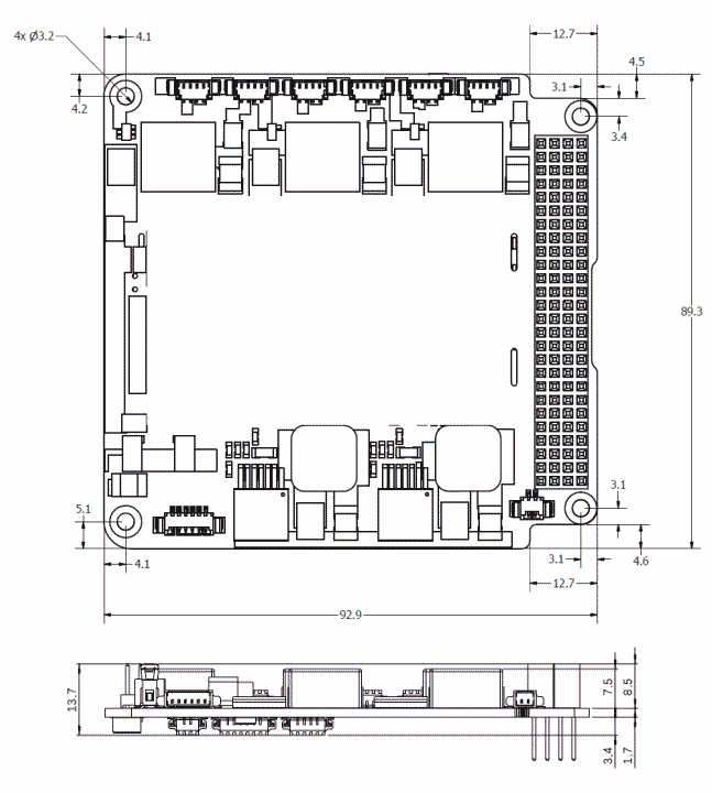
Mechanical Drawing
Dimensions are given in mm.