🚧 This document is still being actively worked on and is subject to change. 🚧
| Responsible |
|
| Last Updated | 10/12/2025, 12:48:54 PM |
| Last Author | Kai Berszin |
Scope
This page contains the rationale and design decisions for the radiation shielding of the OBC main PCB.
Introduction
Many radiation sources in the space environment could cause read-out errors or physical damage. A CMOS camera, for instance, would be impacted by radiation exposure and display white or coloured dots due to the photoelectric effect. One must take into consideration radiation shielding to protect the electronic components.
Space radiation
The space radiation consists mainly of energetic particles and gamma rays. The large proportion of energetic particles (e.g. protons, electrons, alpha particles) prevents further discussion on high-energy rays here.
Model to describe space radiation
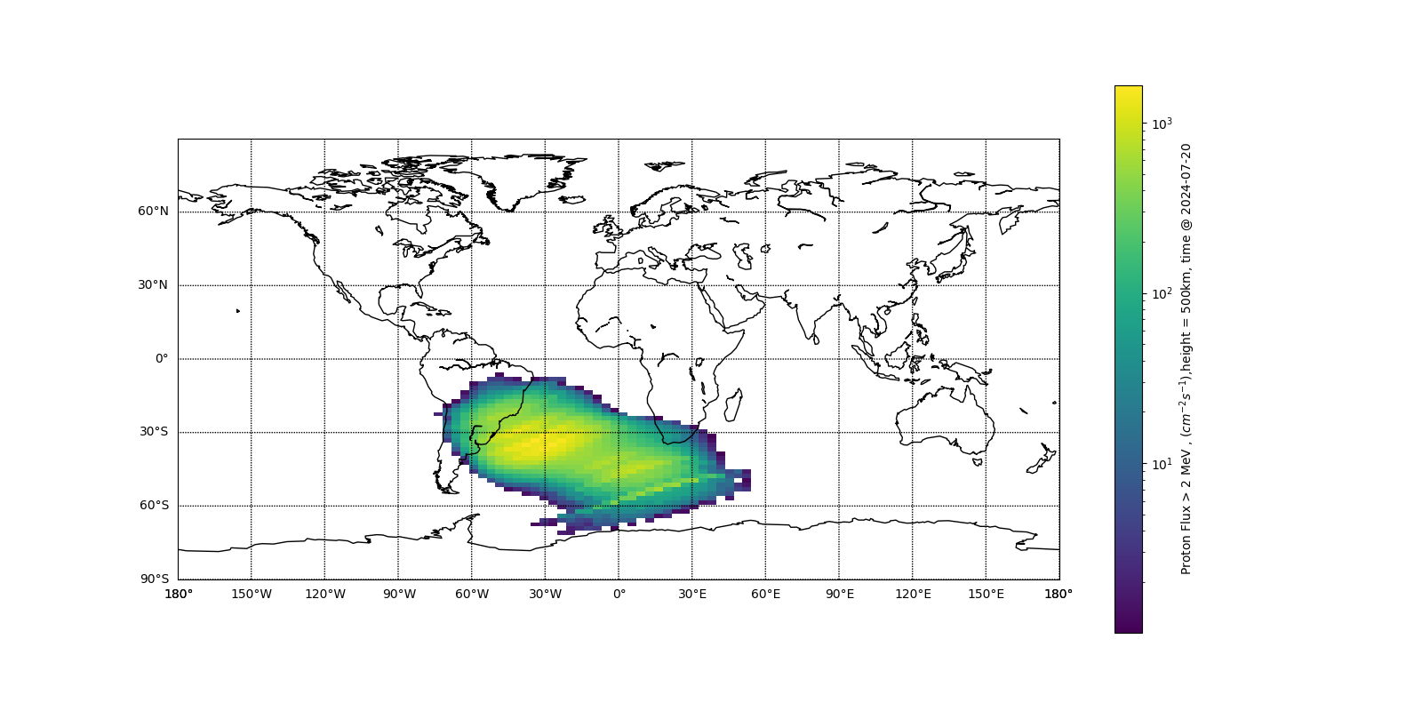
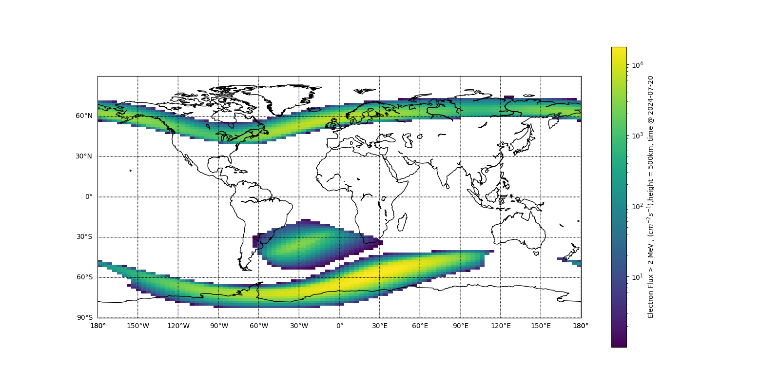
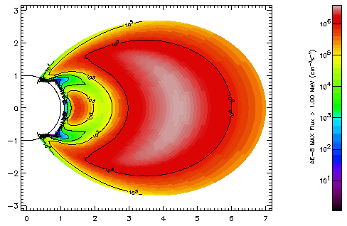
For a low earth orbit mission, one should first have a look into Van Allen radiation Belt. Generally speaking, it is a zone with energetic solar particles captured by the earth's magneto field (geomagnetic field). The Van Allen radiation Belt extends from an altitude above 200km, and depends on the intensity and the longitude/latitude of the geomagnetic field. One could roughly divide the radiation belt model into inner and outer belt. The inner belt contains more energetic proton and the outer belt more electron.


The plots above show that there are two significant regions that might affect the enlarged radiation flux. One is the so-called South Atlantic Anomaly(SAA) that has a lower intensity, and the other is the region on 70S/N latitude that is closer to the outer belt.
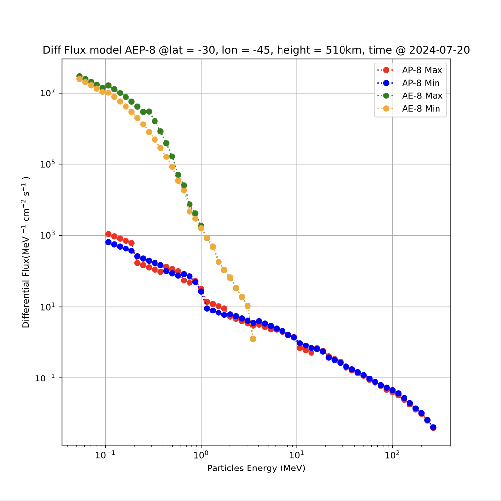
AE/AP-8
AE-8/AP-8 is a model published by NASA in the 1970s to predict the particle flux in the region of the Van Allen radiation Belt. It is based on data from several missions and could provide flux on certain 3D coordinates, with consideration of solar activity in maximum or minimum.It is not a precise model, but it requires less calculation and could be used for a legacy systems.
 P.S. The Plot is in Cylindrical Projection
The AP/AE-8 plot shows that there is a maximum on SAA. It demonstrates a nearly linear relationship to the geomagnetic distribution.
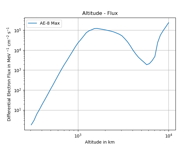
One could notice that the intensity of Electron Flux is not always depends linear to the altitude.
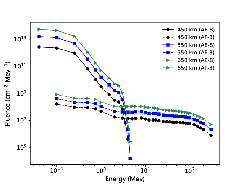
Here we could have some comparison between different models and alitutde in a space mission.
Other models
For the mission, there may be less difference between those models. For the radiation design part, one could skip over the theroy part. However, some of the models are providing a more precise prediction of the space environment that might be useful for further research and application. (explain something about AEP9, SAPPHIRE, etc.)
Reference Data
(py package, platform, etc.)
Experimental Data
(in this part, one could see more experimental data from different provider, e.g. GOES Mission, PROBA)
Radiation Protection
Radiation Effect
(e.g what is protection, how to define it, stopping powers, TIDs etc)
High energy particles will have interaction with spacecraft, and one might categorize them into ionizing effect and lattice displacement.
The lattice displacement is caused by e.g. neutrons or high energy photons. It has a greater effect on the microscale, e.g. the structure of the lattice grid. As an example, lattice displacement will lead to deteriorated PN nodes. One might not discuss too much in this section, since it is not a very significant effect on a LEO mission.
The ionizing effect is caused by e.g. charged particles. Collision with electronic components will release secondary particles. It causes short-term readout error by charged secondary particles.

As a result, one could introduce Total Ionizing Dose(TID) as a reference value of damage. It measures the exposure to radiation environment. Please check the ESA page for detail.
Additionally, one could look at this wiki-plot if they're unclear about the differences between the various radiation dose units.
Stopping power: Bethe-Bloch
(and why just take particle collusion into consideration)
The Bethe formula or Bethe–Bloch formula describes the mean energy loss per distance travelled of swift charged particles (protons, alpha particles, atomic ions) traversing matter (or alternatively the stopping power of the material).
Where
-
: a constant in
-
: effective atomic number
-
: mass of electron, in MeV
-
: ratio of particle velocity to
-
: Lorentz factor
-
: Depends on the kinetic energy with consideration of relativity, one would use the value of as a criteria, if a particle become relativistic.
- while : Cut energy due to finite thickness of absorber in MeV
- while : Maximum transferred kinetic energy
-
: Depends on the kinetic energy with consideration of relativity, again
- while :
- while :
-
: density correction factor