| Responsible |
|
| Last Updated | 10/12/2025, 12:48:54 PM |
| Last Author | Kai Berszin |
ADCS Computer
Scope
This article includes a guide for how to connect the ADCS CubeComputer to a Windows Computer with the CubeSupport Software installed. The article also includes a description for the built in IMU.
Connecting to CubeADCS
This is described in this page.
Alternatives
- I2C
- RS485
CubeSupport Software
- Run executable file in software release bundle (Flash drive??) “\tools\cube-support\cubesupport.exe”
- Connect to CubeSupport via UART or CAN
- Work through “getting started section”
Emulating signals from/to actuators
| Hardware | Inputs | Output |
|---|---|---|
| IMUs | ||
| Magnetometer | ||
| Fine Sun sensors | ||
| Coarse Sun Sensors | ||
| Earth Sensors | ||
| Magnetorquers | ||
| Reaction Wheels |
IMU
The Inertial Measurement Unit is built into the CubeADCS module. Precicely speaking, 2 gyros can be inside the CubeComputer. The DM has one Gyro. No acceleromenter is in this system.
Mathematical Description
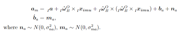
The inertial measurement unit measures the satellite's rotational velocities (gyroscope) and translational accelerations (accelerometer) in the imu coordinate frame I. The measurement model for the 3 axis gyroscope is:

The measurement model for the 3 axis accelerometer is comprised of a linear acceleration term, noise, and two centripetal acceleration terms with (Inertial Frame) being the position of the IMU relative to the Body frame origin expressed in the imu frame: