| Responsible |
|
| Last Updated | 10/12/2025, 12:48:54 PM |
| Last Author | Kai Berszin |
Scope
This is a report that was made when the CubeADCS Development Model was comissioned. Health test were performed.
| Test ID | SAGE-ADCS-TR-9001 |
|---|---|
| Parent Test ID | - |
| Requirement ID | - |
| Test Object | Cube ADCS Development Model |
| Model | - |
| Test Type | Commisioning |
| Testing Session | 1 |
| Facility | HSG Computer Science Lab |
| Date | 18.05.2024 |
| Trial Number | 1 |
| Total Number of Trials | 1 |
Introduction
WereceivedtheCubeSpaceDesignmodelfromthemanufacturerandwanttoprepareitforexperiments. Using documentation to work through setup steps. Windows required.
Test Operators
| Test Role | Project Role | Full Name |
|---|---|---|
| Tester | ADCS Team Lead | Samuel Schönenberger |
| Tester | OBC Team Lead | Gianluca Ielpo |
Test Setup
Ground Support Equipment
| Equipment Name | Identification |
|---|---|
| Computer with Windows 7 or higher with USB-A port | |
| CubeSpace CubeADCS Design Model Power Supply | |
| Oscilloscope | |
| Multi-Meter | |
| Power Supply (10V to 17.6V at current limit set to 1.5A) | |
| DC Power Cable | |
| Cube Support PCB | |
| PCAN USB | |
| UART to USB Cable |
Test Object Configuration
| Configuration Item | Value |
|---|---|
Software Configuration
| Software | Version |
|---|---|
| CubeSupport Software | v4.3.0.3 |
| EOS Satellite Simulation software | v1.13.3 |
| base-bootloader-cube-common-1-computer-5.3 | v1.5 |
| control-program-cube-computer-5 | v5.16.0 |
Test Execution
Test Procedure
| ID | Procedure | Notes |
|---|---|---|
| 1 | Test capabilities of CubeSupport software | - |
| 1.1 | Unzip "dm3-bundle-v4.3.0.3.zip" | Can be found inside the CubeSpaceUSB zip on Sharepoint |
| 1.2 | navigate to sw-bundle-master v4.3.0.3 tools cube-support | - |
| 1.3 | Click cubesupport.exe | - |
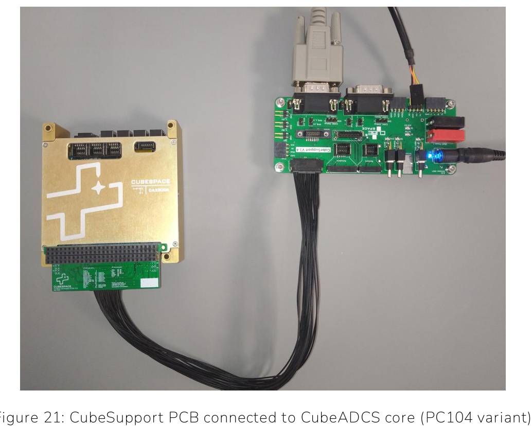
| 2 | Powering up the CubeADCS and connectingit to the CubeSupport PCB | - |
| 2.1 | Set powersupply voltage to 10.0V | - |
| 2.2 | Set current limit to at least 1.5A | - |
| 2.3 | Set all toggle switches on CubeSupport PCB to OFF | OFF = down |
| 2.4 | Connect power supply to Cube Support PCB | Black wire is ground, White dashed line wire is supply-voltage, Connect both to powersupply, Connect otherside to “VBATPower” connector on CubeSupportPCB OR use banana plugs |
| 2.5 | Switch on power supply | - |
| 2.6 | “VBAT Power” LED turns on once power comes in | - |
| 2.7 | Switch “VBAT on” switch to on | on = up |
| 2.8 | “VBAT On”, “5V On” and “3V On” LED are now on | “VBAT On” switch can now be used along with the enable switch (if enable line is connected to CubeADCS)to disable and enable CubeADCS |
| 3 | Connecting via CAN | - |
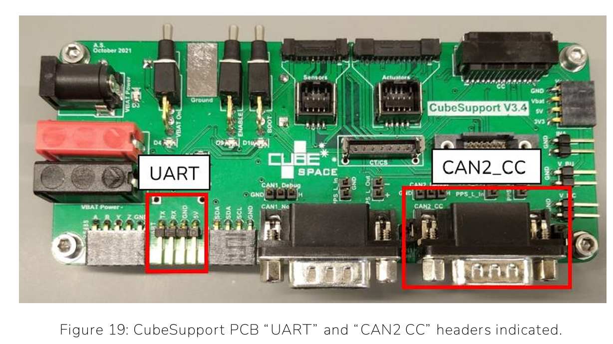
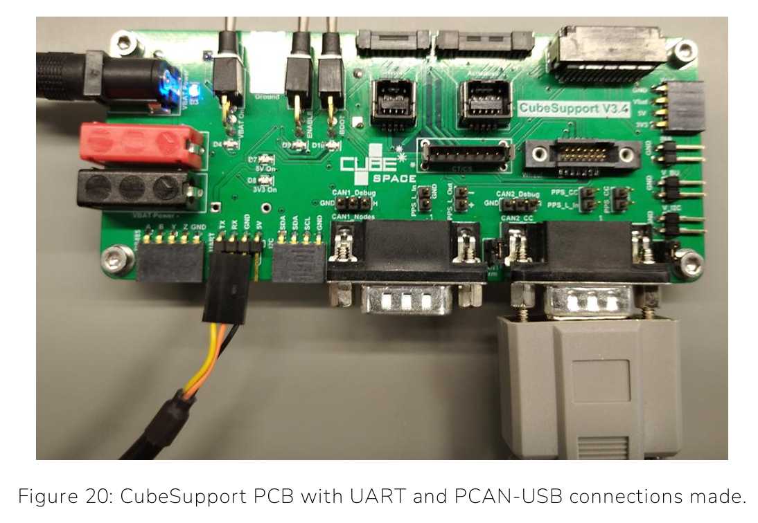
| 3.1 | Use PCAN-USB Cable to connect “CAN2CC” header and USB to connect to laptop | Like in Figures below |
| 3.2 | Turn on power for CubeADCS by “VBAT On” toggle switch on CubeSupport PCB | - |
| 3.3 | Instructions within “CubeSupport” applicationon Page 30-33 in User Manual. | - |
| 4 | Connecting via UART | - |
| 4.1 | Use UART to Serial FTDOUSV cable to connect to “UART” header | Like in figure below |
| 4.2 | Instructions within “CubeSupport” applicationon Page 33-35 in User Manual. | - |
| 5 | CubeADCS Health Check | This can be found on a separate document. |
Test Results
| Time | Objective | Pass/Fail | Comments |
|---|---|---|---|
| - | Powering on CubeADCS | Pass | - |
| - | Connecting via CAN | Pass | - |
| - | Connecting via UART | Pass | - |
| - | Health Checks | Pass | In a different document. |
Anomalies
Only one gyro is present in the DM.
Conclusions
Powering on CubeADCS and connecting with CAN and UART was successful. The Device is healthy.