| Responsible |
|
| Last Updated | 10/12/2025, 12:48:54 PM |
| Last Author | Kai Berszin |
ADCS Computer
Scope
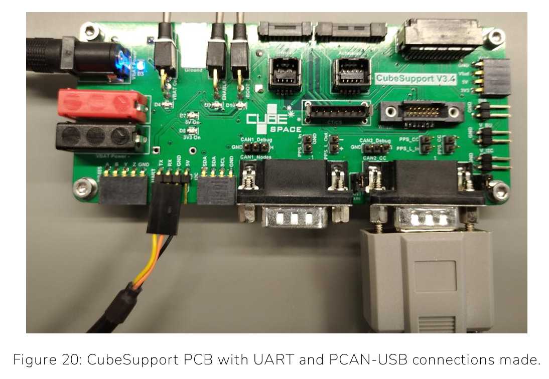
This article includes a guide for how to connect the ADCS CubeComputer to a Windows Computer with the CubeSupport Software installed. It also includes instructions on how to use DS2S in Hardware in the Loop.
Preparation
- Laptop with USB A port and Windows (for CubeSupport software)
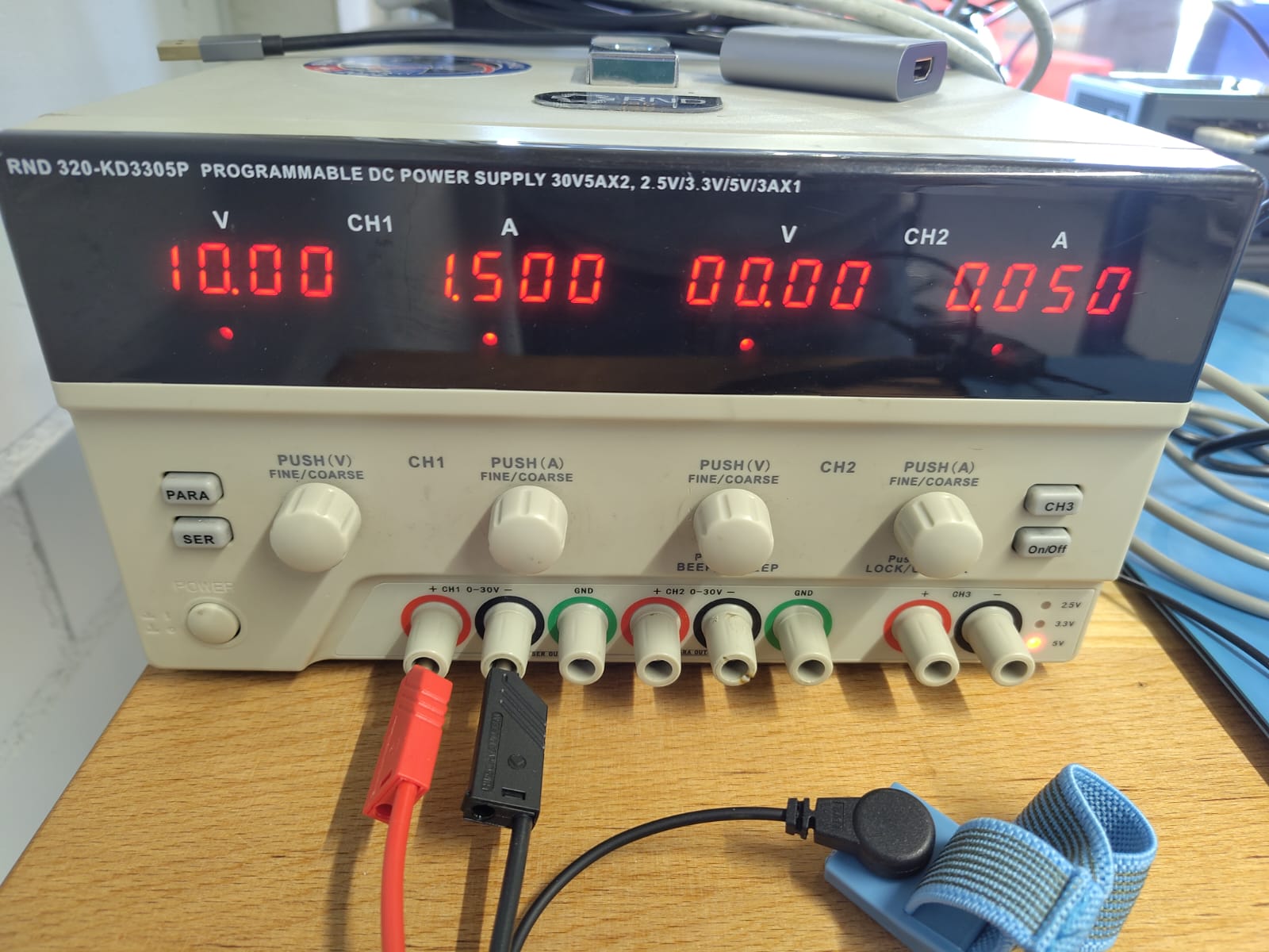
- Power Supply (10V to 17.6V at current limit set to 1.5A)
- Multi-meter or Osciloscope
- Anti-static mat and gloves, anti-static wristband (to ground yourself)
Power
- Set power supply voltage to 10.0V
- Set current limit to at least 1.5A
- Set all toggle switches on Cube Support PCB to OFF (down)
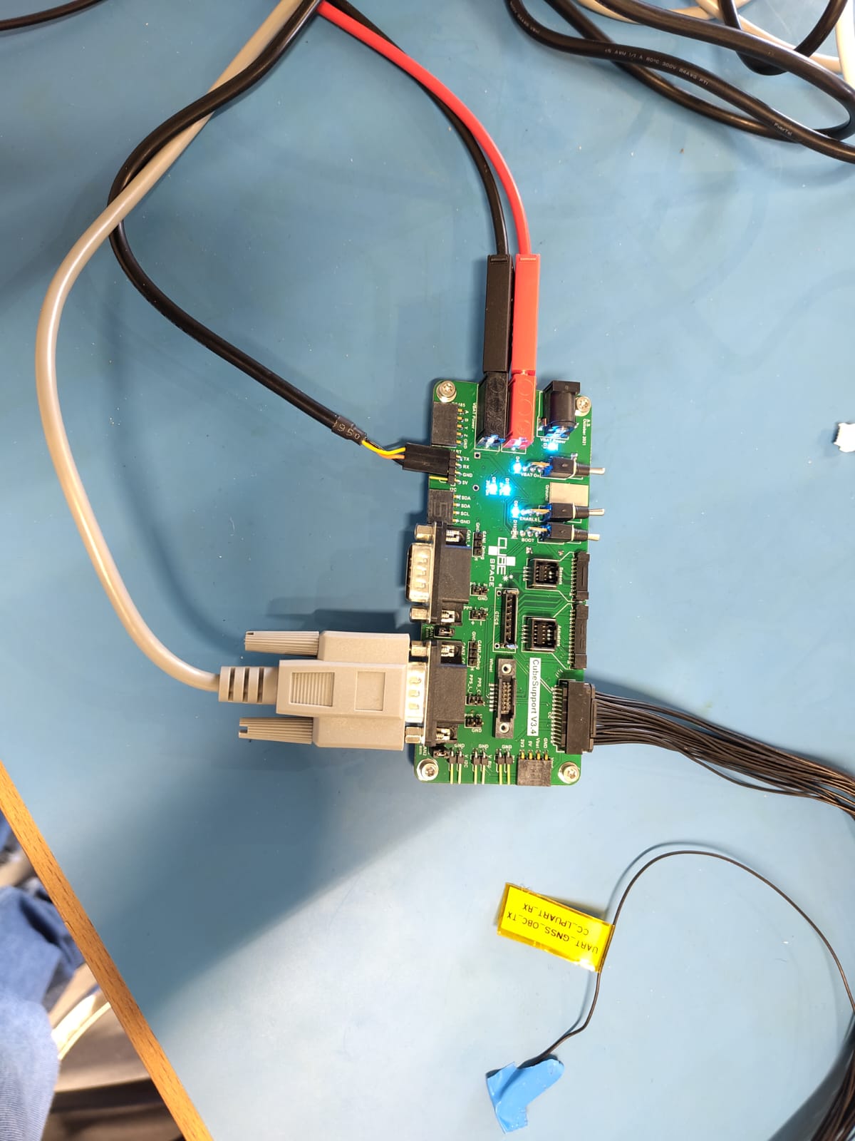
- Connect power supply to Cube Support PCB: Connect red and black banana plug. Alternative: 4.1 Black wire is ground 4.2 White dashed line wire is supply-voltage 4.3 Connect both to power supply 4.4 Connect other side to “VBAT Power” connector on Cube Support PCB
- Switch on power supply
- “VBAT Power” LED turns on once power comes in
- Switch “VBAT on” switch to on (up)
- “VBAT On”, “5V On” and “3V On” LED are now on
- “VBAT On” switch can now be used along with the enable switch (if enable line is connected to CubeADCS) to disable and enable CubeADCS
CubeADCS Interfaces
- Connect CubeADCS to Cube Support PCB via enable cable.
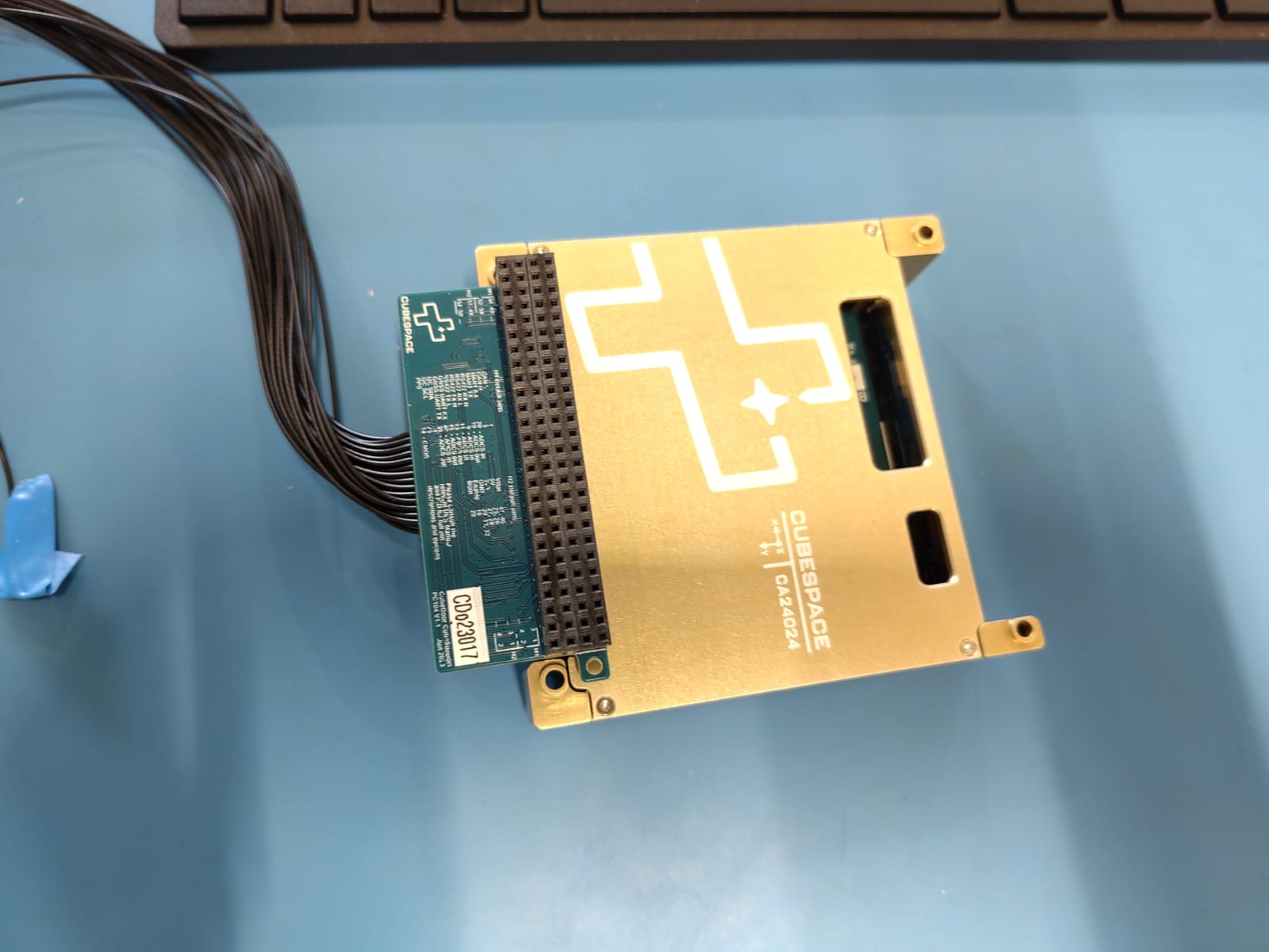
- “Cube Support to CubeADCS harness” (specific to shipment)
- Connect to CubeDoor in CubeADCS core
- Connects to “CC” header on CubeSupport PCB
- CubeConnect board to connect to sensors and actuators
- Sensor from port “Sensor 1” to “Sensor 8”
- Actuator from port “Actuator 1” to “Actuator 4”
- Coarse Sun Sensors (CSS) have dedicated port
- “Coarse Sun Sensors 1 to 5” headers, labelled as CSS0 to CSS4
- “Coarse Sun Sensors 6 to 10” headers, labelled as CSS5 to CSS9
- Anode of each CSS is connected to ground plane of cube computer
- Magnetorquers at Magntorqer pins
- Pins 1 and 2 are CR0
- Pins 3 and 4 are CR1
- Pins 5 and 6 are CR2 The "Auto-Discovery" should find all actuators and sensors that were plugged into the CubeConnect interface.
Connect to your Device
CAN (default)
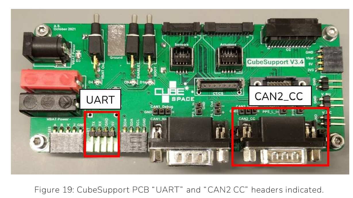
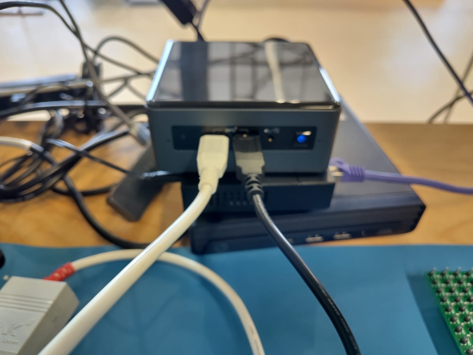
- Use PCAN-USB Cable to connect “CAN2 CC” header amd USB to connect to the mini-PC in the flatsat room
- Turn on power for CubeADCS by “VBAT On” toggle switch on Cube Support PCB
- Instructions within “CubeSupport” application on Page 30-33 in User Manual
UART
- Use UART to Serial FTDO USV cable to connect to “UART” header 1.1. Yellow to TX pin 1.2. Orange to RX pin 1.3. Black to GND pin
- Connect the other side to the mini-PC in the flatsat room.
- Instructions within “CubeSupport” application on Page 33-35 in User Manual
Hardware-in-the-Loop (HIL)
After connecting the mini-PC and the CubeComputer DM to the CubeSupport PCB, we can test our script with the hardware in the loop.
- Open "D2S2 Satellite Simulator"
- Open a Scenario by clicking the second button from the left.

- Choose a D2S2 file.
- Execute the script to turn the regular scenario into a HIL scenario. 4.1 Click on the fourth button from the left. 4.2 From this list choose "HIL Conversion" 4.3 Click execute.
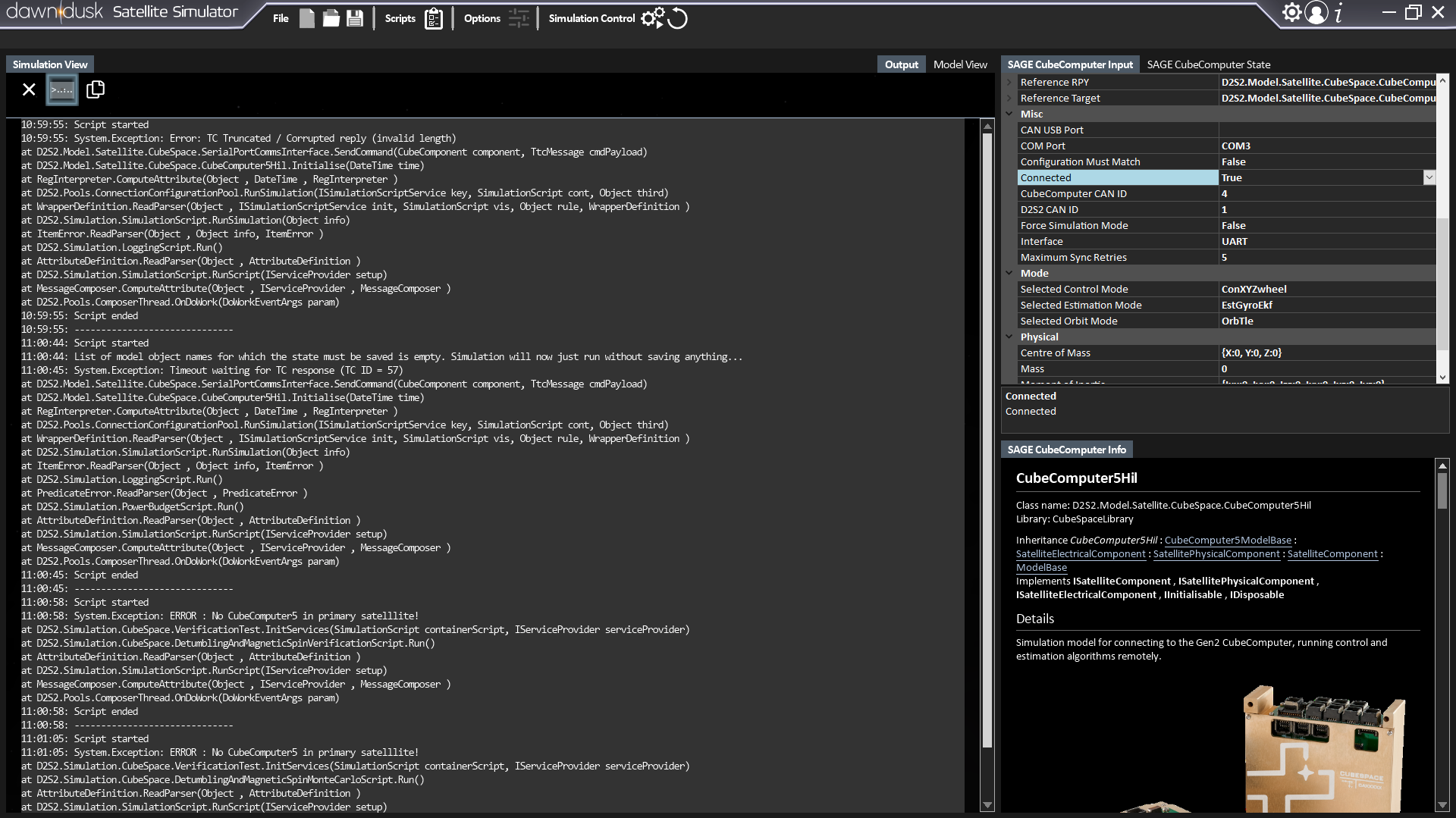
- Set the setting like in the following image (on the right) to connect the CubeComputer to D2S2.
Problems
A major issue persists in the simulation of scheduled scenarios in HIL mode. Here, when executing step 4, the "SAGE CubeComputer" object is converted from a "CubeComputer5" type object to a "CubeComputer5Hil" type object. This causes errors in the subsequent execution of the HIL-converted scripts, where the schedule expects a "CubeComputer5" object whithout it existing. This is despite the fact that the schedule definition only expects the "SAGE CubeComputer" object regardless of type. Thus, is unknown what could solve this issue. This problem also happens when using CubeSpace's own detumbling scripts with a HIL converted scenario. This issue will be adressed when the licence for D2S2 is acquired again.
Reward for reading